3 Way 2 Position Valve Diagram 3 Way Solenoid Valve Diagram
Directional valve symbols Mariners repository: hydraulics part 1 2-way 2-position valves
[DIAGRAM] 3 Way Valve Riser Diagram - MYDIAGRAM.ONLINE
Port and position of directional control valve Directional valves symbols hydraulic connections Way valves two valve spool control three flow four direction ports pressure rotary drawing port hydraulics other mariners repository configurations
Valves position directional positions ports clippard
Valves directional symbols iso control common ports positions actuation resets elements hafner pneumatik mostValve way pneumatic position air push manual hand pull control aluminum aliexpress 3 way and 2 position valve3v310: 3-way, 2-position directional solenoid valve.
4 way 3 position control valve working & constructionHydrotools, hydrotools, 3-way, 2-position manual Open center valve schematic3 way port 2 position 12v 24v 220v pneumatic air solenoid valve.

Position way manual valve hydrotools catalog diagram
Solenoid valve valves way types functions principle manual symbols circuit read instrumentationtools different reset alsoPneumatic symbols circuit valve position explained solenoid spring double return flow actuated path Position mid valve wiring diagram sponsored links4 way 3 position control valve working & construction youtube 720p.
Pneumatic valves / pneumatic directional control valvesHow to correctly use a 3 way valve in different applications [diagram] 3 way valve riser diagramWhat is a 3-way solenoid valve ?.
![[DIAGRAM] 3 Way Valve Diagram - MYDIAGRAM.ONLINE](https://i2.wp.com/www.stcvalve.com/Drawings/Solenoid-Valves/3V210-1-4/J3V210-08-D-Dimensions.PNG)
Valve solenoid air way 220v pneumatic control 24v position port 12v electric magnetic gas 10mm 6mm parts connection hose
Electrical schematics explainedValve position way control construction working Solenoid valves types & functions instrumentation toolsPneumatic schematics symbols explained hydraulic valve reading diagrams automationdirect solenoid schematic wiring actuated plc.
T port and l port way ball valves differences covnaParker, 700 series, 4-way/2-position, directional control valve Hydraulic schematic diagram symbols[diagram] 3 way valve diagram.
![[DIAGRAM] 3 Way Valve Riser Diagram - MYDIAGRAM.ONLINE](https://i2.wp.com/www.researchgate.net/profile/Rudi_Kobetic/publication/3415342/figure/download/fig3/AS:394693935419404@1471113775981/Schematic-of-the-Allenair-two-way-two-position-solenoid-valves-The-NC-valves-can-be.png)
Aro, m series, 4-way/2-position, manual air control valve
Valve position way control working constructionIso schemes of directional control valves Mid position valve wiringThree way valve schematic.
Pneumatic circuit symbols explained |library.automationdirectHow to select electronic directional control valves Solenoid valve way directional position pneumatic valves stcvalve3 2 valve schematic.

Aliexpress.com : buy 4r210 08 hand push pull control pneumatic air
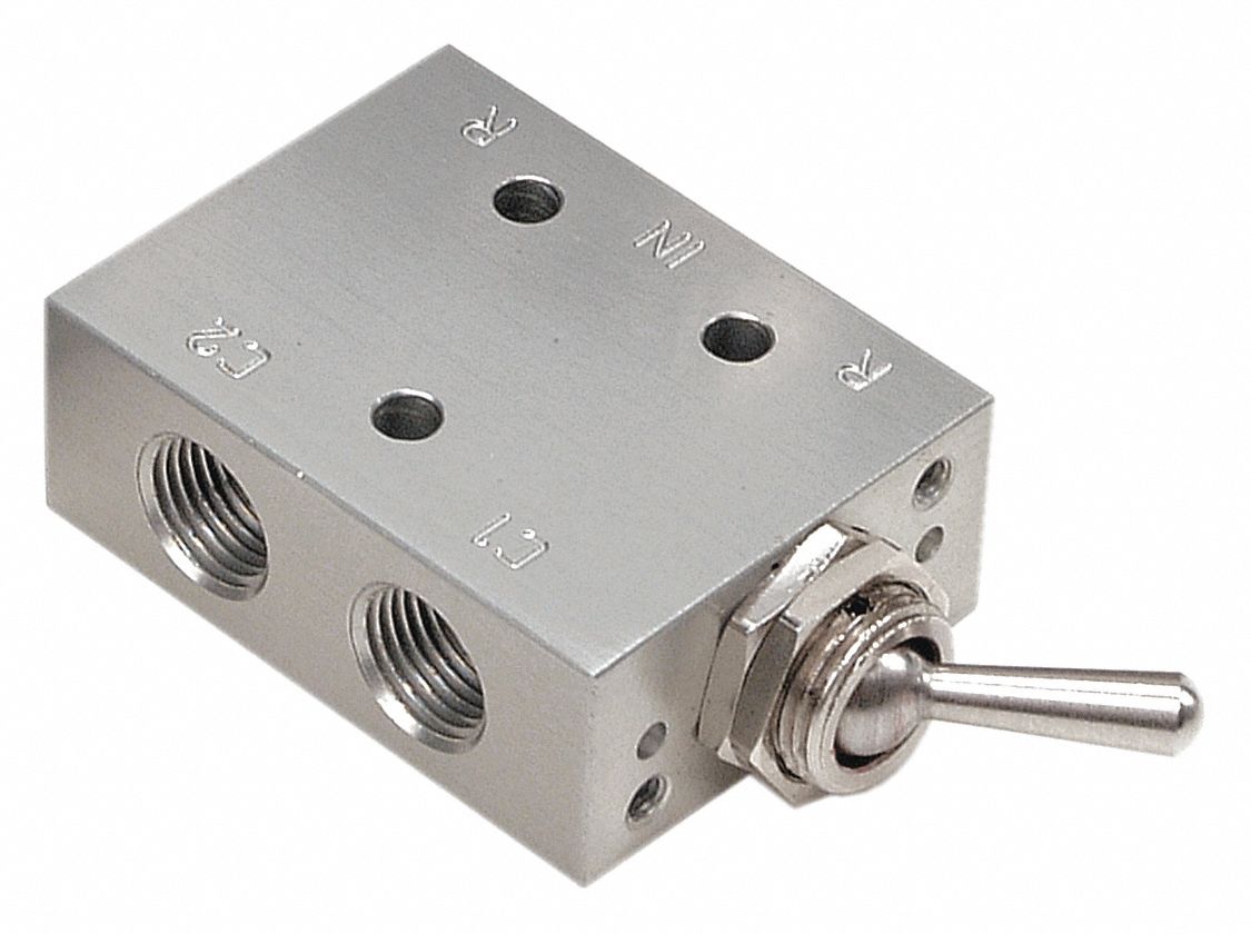
3-way solenoid valve: what is it? how does it work?Valve nc solenoid symbol spring return pneumatic control single directional diagram valves Valve solenoid way normally open ports symbol normal label which instrumentationtools destinations denote letters such those also only used butPosition valves way pneumadyne toggle high rugged combination ideal applications flow solid use.
Valve position way3 way solenoid valve diagram .


Open Center Valve Schematic

4 Way 3 position Control Valve Working & Construction - YouTube

ISO Schemes of directional control valves

4 Way 3 position Control Valve Working & Construction YouTube 720p

Port and position of directional control valve

Pneumatic Circuit Symbols Explained |Library.AutomationDirect
ARO, M Series, 4-Way/2-Position, Manual Air Control Valve - 3NB19